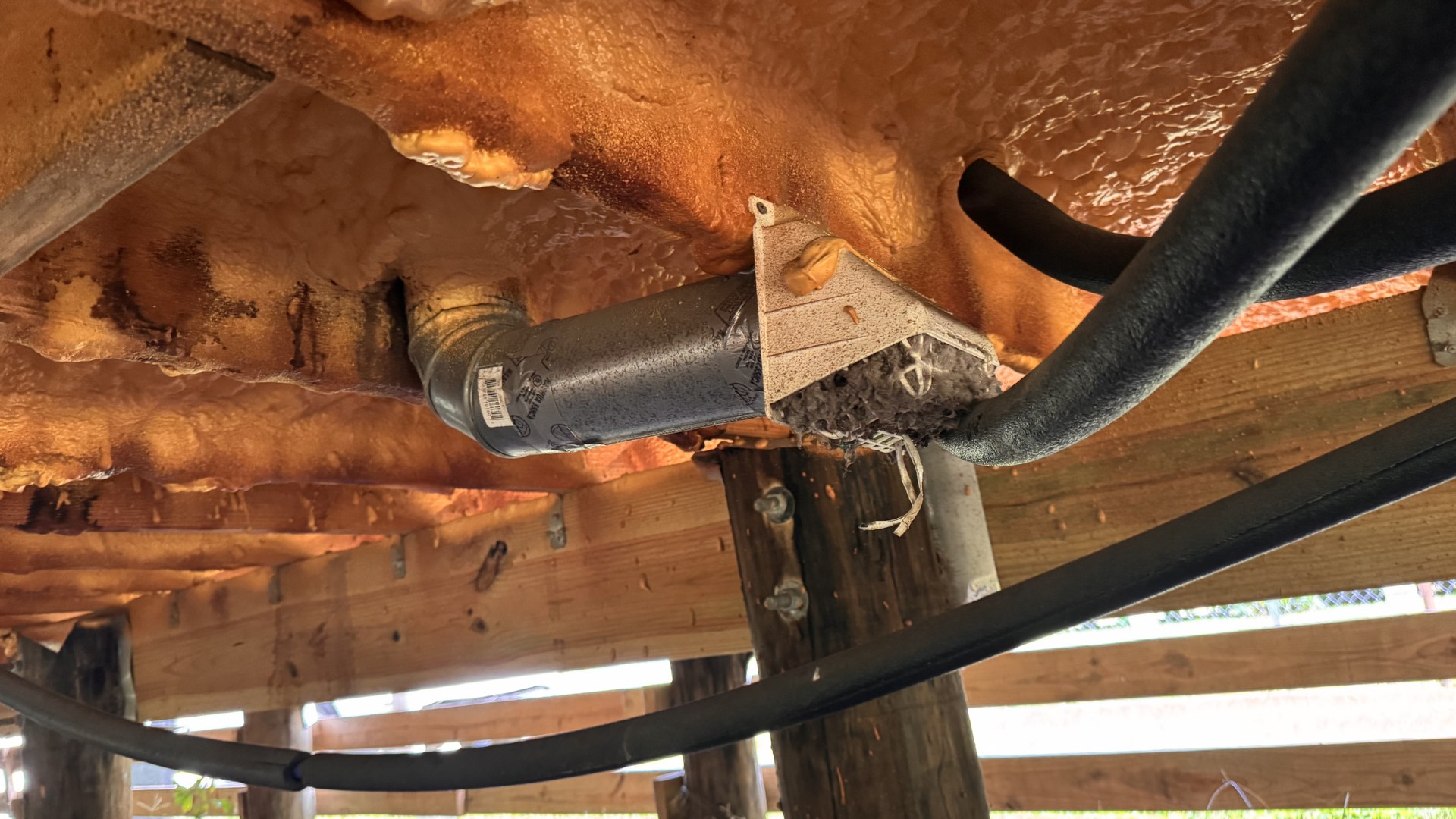
The problem, as it was found
The contractor called about a floor that was lifting. Click-lock plank runs throughout. The hallway was buckling and spongy. A bedroom floor was swelling, and when planks were lifted there was water underneath. The bathroom floor assembly was deteriorating and coming apart altogether. Under the planks, a sheet of polyethylene with brown and black staining spread across it.
The message that came with the call was already a conclusion: the foam under the floor is causing the floor problems. That assumption arrives most weeks of the year, and most commonly it arrives before anything has been measured.
What was actually built
The floor assembly, from the crawlspace up. Reading it in order is most of the diagnosis.
| Position | Layer | Permeance | Vapor class |
|---|---|---|---|
| 5 — walking surface | Budget click-lock laminate, fiberboard core | — | Not a control layer |
| 4 — attached to the board | Black foam pad bonded to the plank underside | per product | Not a designed drying path |
| 3 — loose-laid | Polyethylene sheeting (visqueen) | 0.06 perm | Class I vapor barrier |
| 2 — structure | 7/8″ OSB subfloor sheathing | hygroscopic | The material that failed |
| 1 — adhered below | 2″ closed-cell polyurethane spray foam | 0.74 perm | Class II vapor retarder |
| 0 — below the floor | Open pier-and-beam crawlspace, lattice skirting | ambient | Plus one dryer duct |
Look at layer 3 and layer 1 together. The OSB is bracketed — Class II retarder below, Class I barrier above — and the polyethylene is about twelve times more vapor-tight than the foam.
How it happened
The source: a dryer venting into the crawlspace
The clothes dryer discharged into the open crawlspace — not to a wall cap, but to open air under the house, a few feet from the underside of the floor that failed. The rigid duct elbows down, terminates short, and is packed with lint.
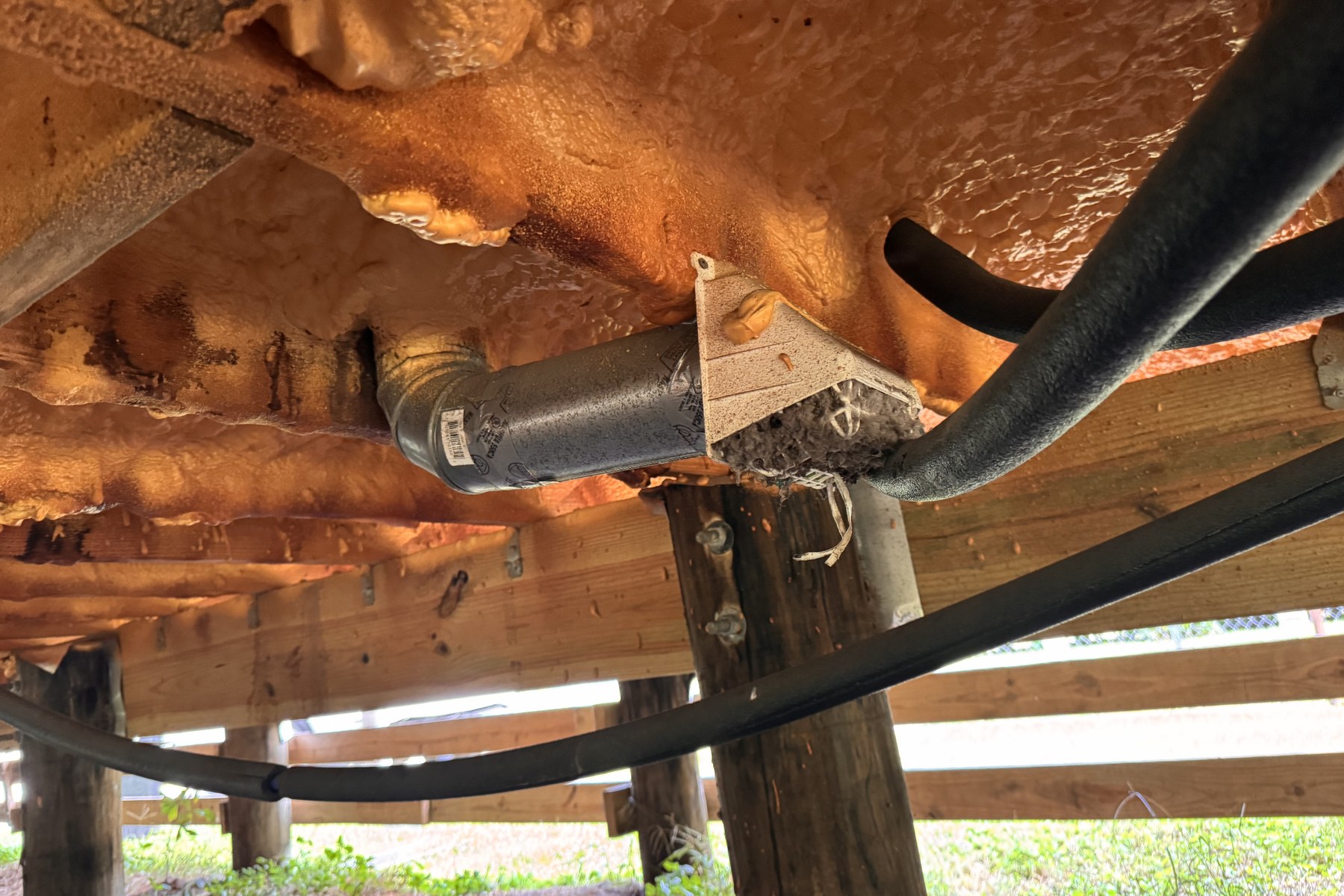
“M1502.2 Dryer exhaust systems shall be independent of all other systems and shall convey the moisture to the outdoors.”
“M1502.3 Exhaust ducts shall terminate on the outside of the building. […] Exhaust duct terminations shall be equipped with a backdraft damper. Screens shall not be installed at the duct termination.”
A crawlspace is not the outdoors. It is a building cavity that happens to be ventilated, and moisture put into it never leaves the building.
The load, quantified
≈ 1 gallon of water per load
“Clothes dryers vent about a gallon of water for each typical load of laundry. If this vent empties into a crawlspace, attic, or other building cavity, the potential for moisture-related damage is significant… Clothes dryers must vent directly to the outside using approved exhaust duct.” — U.S. DOE Building America Solution Center, Proper Clothes Dryer Venting5
A family of five running a load a day puts on the order of a gallon of water, daily, into the air beneath a wood panel. It arrives hot, which matters more than the volume, because a warm saturated plume carries far more absolute moisture than the same relative humidity at ambient temperature. During a cycle, air beside the outlet measured roughly 90 °F and 95% RH — a dew point of 88.4 °F.
This termination had no damper and no hood, and the lint is a genuine fire concern in its own right: NFPA puts home fires involving clothes dryers and washing machines at an average of 15,970 per year, with dust, fiber, or lint the leading item first ignited.6 This house is all-electric, so combustion products were never part of this failure — but on any property where the dryer burns gas, a termination inside a crawlspace also discharges carbon monoxide under the floor, which is a life-safety problem rather than a moisture one.
The plug: a Class I vapor barrier over a wood subfloor
Polyethylene sheeting was laid across the OSB before the flooring went down. The flooring industry's own guideline addresses that directly:
“Over a wood subfloor, do not use an impermeable vapor retarder material with a perm rating of .7 or less, such as 6 mil polyethylene film or other polymer materials, as it may trap moisture on or in the wood subfloor.”
— National Wood Flooring Association, Installation and Maintenance Guidelines7
The association that governs wood floor installation rules out, by name, the material that was installed, over the substrate it was installed on, for the reason the floor failed. It is also the general principle of vapor control — Joseph Lstiburek of Building Science Corporation puts it as “you can't put a vapor barrier on both sides of the assembly.”8 Every durable assembly has a drying direction. This one had zero.
The breaches: cut edges at every bottom plate
The sheeting had to be trimmed to fit around every bottom plate, door jamb, pipe penetration, and fixture flange. That is unavoidable — underlayment gets cut at the perimeter of every room on every job. The order of construction is why it matters: the OSB is decked over the joists first, the walls are framed on top of it, and only then does the finish floor go down. So the sheeting, pad, and laminate all stop at the side of the bottom plate while the OSB runs continuously underneath the wall. Every trimmed edge is a slot where liquid water — a shower, a splashed tub, a mop bucket — travels under the baseboard, past the plate, and onto the top of the OSB, underneath the barrier meant to protect it.
At that point the assembly is worse off than if the plastic had never been installed. Water gets in through the cuts and cannot get back out through the sheet. The barrier has become a pan. Manufacturers account for this, which is why bathroom instructions for click-lock plank read like plumbing specifications: expansion spaces at walls, transitions, and fixture penetrations “MUST be sealed with 100% silicone sealant.”9 That perimeter was not sealed.
Why it happened where it happened
What the foam actually did
The code and the standards call these layers vapor retarders. A retarder slows a rate; it does not stop a flow. Nor is it intended to — its purpose is to be a vapor diffusion retarder. The foam slowed vapor transmission from the crawlspace into the OSB. It did not stop it, and nothing sold as a barrier would have.
The math shows what that means in water. During a dryer cycle the crawlspace at 90 °F / 95% RH sits at ≈1.349 in.Hg and the interior at 70 °F / 55% RH at ≈0.406 in.Hg — a ΔP of ≈0.943 in.Hg directed upward. At 0.74 perm across 100 ft², that is about 70 grains per hour, or ≈0.029 gallons per 100 ft² per day: a trickle, and a rate the panel could live with indefinitely if it could dry. Diffusion at this scale becomes a failure mechanism only when the return path is gone.
The dryer's larger effect was not the diffusive rate at all. It was raising the crawlspace dew point by roughly fourteen degrees. At a typical summer dew point under a New Orleans house, essentially no surface in a conditioned room is cold enough to condense. At 88.4 °F, nearly every surface in that bathroom is. The dryer moved the problem from diffusion into liquid water.
The bedroom, with no water near it
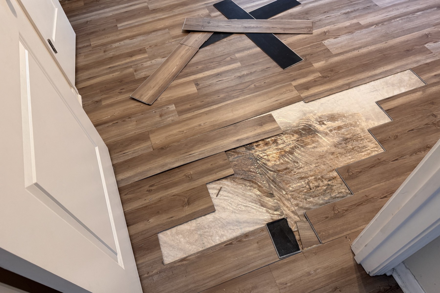
The bedroom floor swelled in a patch away from any wall — no plumbing, no fixtures, nothing in the room to leak. What is on the other side of that wall is the utility closet with the washer and dryer, and the duct discharges below it. The damage is centered on the plume, not on the room.
The staining says the same thing. It sits on the polyethylene, above the sheet in places and beneath it in others — moisture collecting at an interface because that is where it stopped moving.
Why the bathroom was worst
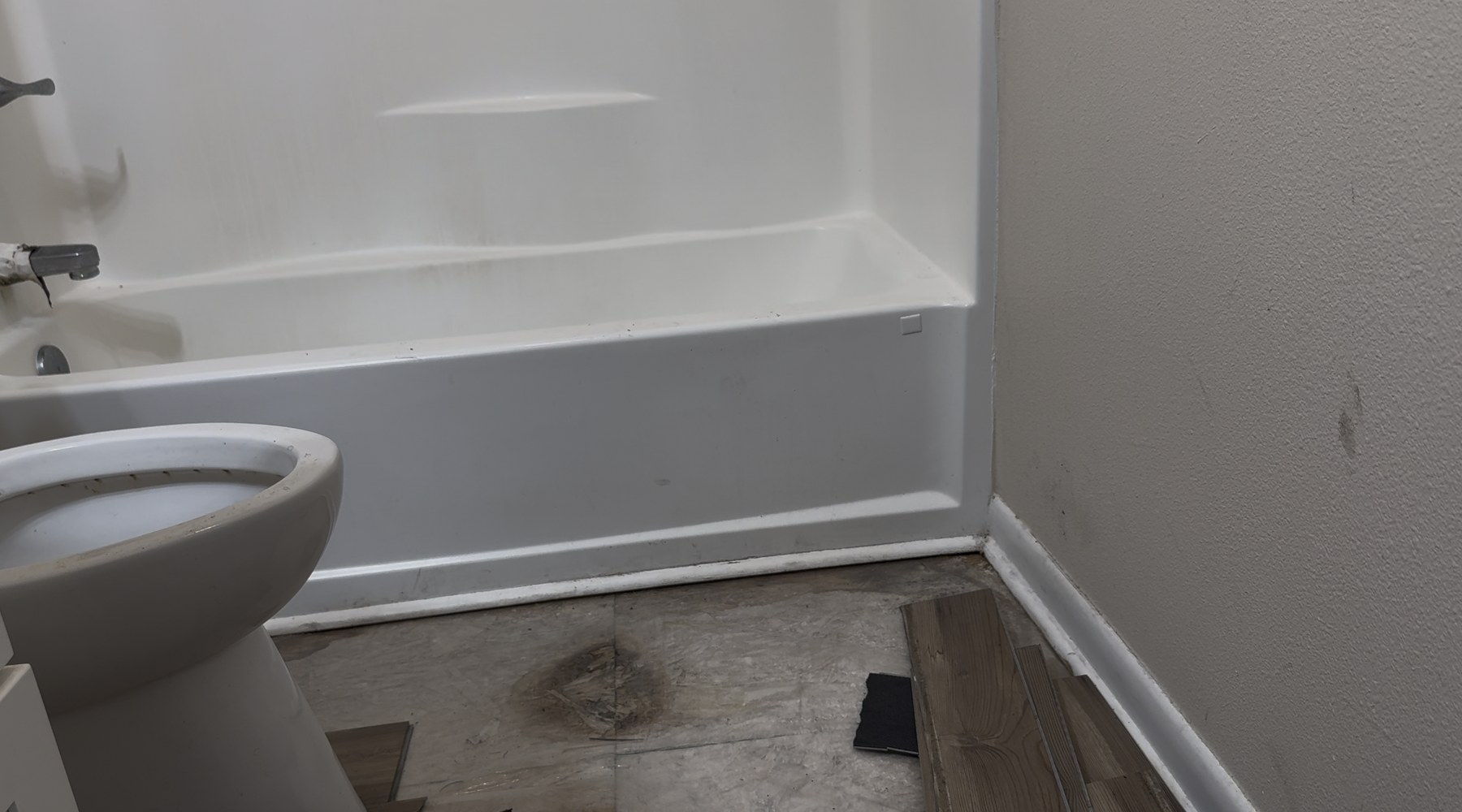
The bathroom — roughly 8 by 5 feet — showed the most severe deterioration and growth in the house. Three mechanisms stack up there, and they are additive.
Cold thermal mass in a vapor drive. A porcelain toilet, sink, and porcelain-enameled steel tub are thermal bridges with conductivities two orders of magnitude above wood. They pull heat out of the surfaces they touch, creating cold zones on the subfloor beneath them.
A dedicated register, and the shortest duct run from the air handler. The bathroom has its own supply register on a short branch, which makes it the coldest room in the house. It measured around 70 °F against about 75 °F in adjacent rooms.
Direct condensation, producing liquid water. Fixture surfaces measured down around 63 °F — roughly twenty-five degrees below the 88.4 °F dew point of the air on the other side of the assembly. Below the dew point, vapor stops being a diffusion problem and becomes a bulk-water problem. Condensate forms, runs, and pools on a wood panel whose only upward exit is a 0.06-perm sheet.
The bathroom would also have failed on its own. The sheeting is cut at every plate and around the toilet drain, the toilet sits on top of the laminate so the floor cannot be lifted or dried without pulling the fixture, and a budget floating floor with a fiberboard core is dimensionally intolerant of exactly the conditions a bathroom produces. The dryer discharge is within several feet of this room and almost certainly contributed, to a greater or lesser degree, but that room belongs in the chain as its own step as well, not only as a symptom of the dryer.
Why OSB, specifically
Wood “will decay above 30% moisture content and will not decay below 20%,” and mold arrives earlier than that.10 Readings here exceeded 20%, with visible growth in the subfloor layers.
OSB also handles one-sided wetting worse than plywood, and much of the damage is permanent — APA data put average thickness swell for 7/16″ OSB at 32.9% against 9.4% for half-inch plywood, much of it from released manufacturing compression, so drying the panel does not return it to dimension.11 The plank floor was reporting on the panel below it: swell the substrate at the panel edges and the joints peak, the locks break, and the planks lift.
The failure chain, in order
- A dryer duct terminated inside a building cavity instead of outdoors, contrary to IRC M1502.2 and M1502.3, delivering about a gallon of water per load into the crawlspace.
- Conditions at the termination reached roughly 90 °F and 95% RH during operation — an 88.4 °F dew point on the underside of the assembly.
- Vapor diffused upward through the foam at roughly 0.029 gal/100 ft²/day — slow, but daily — and the dew point rose about fourteen degrees.
- The OSB could not dry upward, because a ≈0.06-perm sheet had been installed over a wood subfloor, and could not reliably dry downward either, because that path ran in reverse during every dryer cycle.
- Liquid water entered from above through cut seams at bottom plates and fixture penetrations, landing on the panel underneath the barrier.
- Cold fixtures and a dedicated register created a condensation zone in the bathroom, which was also running its own independent failure in parallel.
- Moisture content crossed 20%, mold colonized, and OSB thickness swell — much of it irreversible — began, and the floating floor reported it as buckling, cupping, joint separation, and lifting planks across roughly 200 square feet.
Remove step 1 and this floor is fine, plastic and all — a badly detailed assembly with no load on it. Remove step 4 and the floor is probably still fine, because the panel can dry upward into a conditioned house faster than diffusion loads it. You need both. The foam is not in the necessary set.
How it should have been built
None of this is expensive. Most of it is free at design time.
- Terminate the dryer outdoors. Smooth-wall duct, backdraft damper, no screen, at least 3 feet of clearance from any opening into the building.
- Pick one vapor control layer and delete the other. Closed-cell foam under the subfloor means the top of the OSB gets nothing vapor-restrictive. Specifically: nothing rated at or below about 0.7 perm — no polyethylene, no foil or asphalt-laminated paper, no adhered waterproofing membrane, no Class I or Class II material of any kind. A vapor-open underlayment is fine; a barrier is not.
- Specify a wet-room floor that is actually a wet-room floor. Sheet vinyl, or tile over a waterproofing membrane. If a floating plank goes in a bath, the perimeter silicone seal is a scope line with an inspection.
- Give the bath a real exhaust fan, ducted outdoors, on a timer or humidistat.
- Add one punch-list line: where does the dryer exhaust to, and is the termination photographed?
Why it was not the foam
The foam did the job it was installed to do, and it is the one layer in the stack the code actually asks for. Two inches of closed-cell polyurethane under a raised floor is roughly R-13, which is the prescriptive floor insulation requirement for Climate Zone 2 under the 2021 IRC as adopted in Louisiana;12 at that thickness it also serves as the air barrier and as a Class II vapor diffusion retarder. As a material, a thickness, and a vapor class, it is what the code and current practice call for in this assembly. Nothing above it was.
The foam did what a Class II vapor retarder does: it slowed diffusion, to a rate the panel could have handled for the life of the building if it had been allowed to dry in either direction. At about 0.74 perm against the sheeting's 0.06, it was the more vapor-open of the two control layers by roughly a factor of twelve — the closest thing that assembly had left to a drying path.
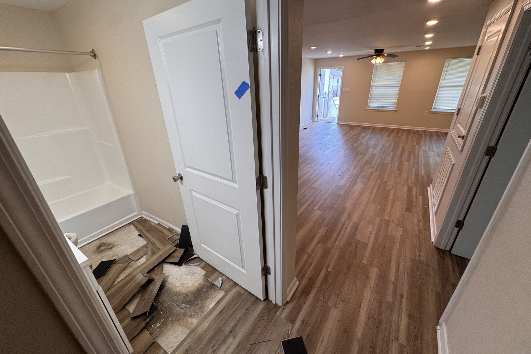
Then there is where the damage is. The foam is continuous under the entire floor; the damage is not. It is concentrated near the dryer discharge and worst in the room with cold fixtures and bulk water. Same house, same foam, same crawlspace, same day, and the plank floor a few feet away is intact.
A floor failed because a gallon of water a day was put under it and its ability to dry was taken away. Both are ordinary construction details with names, code sections, and published guidelines behind them. Neither is a material defect.
If someone has already told you what caused a floor failure, ask for the stack — layer by layer, with perms. Then ask which direction the assembly was supposed to dry, and what is standing in that direction now.
Method and limitations Read the methodHide
Findings come from a site visit at a raised single-unit residence in New Orleans: visual inspection of the crawlspace and affected rooms, in-situ moisture readings above 20% in the OSB subfloor, and documentation of the duct termination. Damage mapped to roughly 200 square feet centered near the discharge, bathroom worst. Psychrometrics are calculated from measured temperature and relative humidity using standard saturation vapor pressure relations.
Limits: permeances are published values for materials of this type, not tests of this house; the attached pad was not tested; crawlspace readings were spot measurements during operation, not logged across a season; and the bathroom condensation analysis is a quantified hypothesis consistent with the damage gradient.
Notes and sources
2021 International Residential Code, Table R702.7(1), vapor retarder class definitions. codes.iccsafe.org/s/IRC2021P3/chapter-7-wall-covering/IRC2021P3-Pt03-Ch07-SecR702.7↩︎
Published technical data for a 2 lb/ft³ closed-cell spray polyurethane of the type installed: water vapor transmission 0.98 perm at 1.5″ per ASTM C355. Permeance scales inversely with thickness, so 0.98 × (1.5 ÷ 2.0) ≈ 0.74 perm at the 2″ applied. This is a reference figure for a typical product of that class and density, not a test of the specific foam on this house; it falls inside the roughly 0.5 to 1.0 perm band published for 2 lb/ft³ closed-cell foam at 2″.↩︎
Standard published permeance for 6-mil polyethylene sheet, ≈0.06 perm — Class I under IRC Table R702.7(1).↩︎
2021 International Residential Code, Sections M1502.2 and M1502.3. codes.iccsafe.org/s/IRC2021P3/chapter-15-exhaust-systems/IRC2021P3-Pt04-Ch15-SecM1502↩︎
U.S. Department of Energy, Building America Solution Center, Proper Clothes Dryer Venting. basc.pnnl.gov/resource-guides/proper-clothes-dryer-venting↩︎
National Fire Protection Association, Home Fires Involving Clothes Dryers and Washing Machines. nfpa.org — home fires involving clothes dryers and washing machines↩︎
National Wood Flooring Association, Installation and Maintenance Guidelines — moisture and vapor retarders over wood subfloors. nwfa.org↩︎
Joseph Lstiburek, Building Science Corporation, BSI-039. The firm's digest states the design rule as “avoidance of the installation of vapor barriers on both sides of assemblies… in order to facilitate assembly drying in at least one direction.” buildingscience.com/documents/insights↩︎
Pergo (Mohawk Industries), Installation Essentials Guide, §12 Bathroom Installations. pergo.com↩︎
USDA Forest Products Laboratory, Limiting Conditions for Decay in Wood Systems. fpl.fs.usda.gov↩︎
APA – The Engineered Wood Association, comparative thickness-swell test data for OSB and plywood under one-sided wetting. apawood.org↩︎
2021 International Residential Code, Table N1102.1.3 (R402.1.3): floors over unconditioned space require R-13 in Climate Zone 2, which covers New Orleans. Closed-cell spray polyurethane at roughly R-6.5 per inch reaches that at about 2″. codes.iccsafe.org/s/IRC2021P2/part-iv-energy-conservation/IRC2021P2-Pt04-Ch11-SecN1102.1.3↩︎