
The complaint arrives in a predictable shape. One bedroom never cools. The thermostat is satisfied and the room is not. Somebody puts a hand over the register, feels a lazy drift of cold air, and reaches the obvious conclusion: the equipment is undersized, or the house is leaky, or flexible duct was a cheap choice and this is what cheap buys.
The measurement usually says something narrower and more fixable. The duct feeding that room is the correct diameter, the correct insulation value, and the correct material. It is simply longer than the distance it has to cover, and the extra length is still in the attic, gathered into gentle waves nobody thinks to look at.
The short version
- Flexible duct pulled fully stretched tests within about two percent of rigid sheet metal of the same diameter under ASHRAE Standard 120 test conditions.2 As a material, it is not the problem.
- Compress that same duct along its length by roughly four percent — leave about ten inches of slack in a twenty-foot run — and pressure loss rises sharply. A six-inch duct at a typical branch pressure goes from around 110 CFM to around 70 CFM.3
- Push past four percent and laboratory work puts the penalty at two to ten times the pressure loss of the stretched duct, with some configurations worse than ten.1,2
- The trade's own installation tables treat everything from zero to four percent as “fully extended” and tell the designer to use the published friction rate unchanged.5 That is where the paperwork and the measurement part company, and it is the finding this article is really about.
- None of it is visible from the attic hatch. ASHRAE's own duct design guide says compression “is difficult to see or measure when installed.”7 So you measure pressure and airflow instead of trusting your eyes.
The ground rule: one duct, installed two ways
I am going to keep returning to a single length of insulated flexible duct installed two different ways, because holding the material constant is the only honest way to separate a workmanship problem from a material problem. Same manufacturer, same diameter, same R-value, same air handler. One version pulled straight and tight between supports. The other left long, drooping a little between straps, taking a bend or two tighter than it should.
If those two installations move very different amounts of air — and they do — then whatever is happening is not a property of flexible duct. It is a property of length management. That distinction matters commercially, because it changes what you should be asking for and what you should be paying for. It is entirely possible to specify an expensive rigid-metal system and get mediocre airflow, and entirely possible to specify flexible duct and get airflow that matches the design.
This piece is about friction inside the duct — the resistance the air feels as it travels. It is not about duct leakage, which is a separate account with its own math, discussed below.
What slack actually does to the inside of a duct
Flexible duct is a wire helix with a plastic liner stretched over it, wrapped in insulation and an outer jacket. When the liner is pulled taut, the helix pitch opens up and the inner surface comes close to smooth. The air travels down something that behaves, aerodynamically, a lot like a pipe.
Leave the run long and the helix closes up like an accordion. The liner between the wires no longer stretches flat; it bulges inward into the airstream as a repeating series of ridges. Every one of those ridges sheds a small vortex. The air is no longer sliding along a wall — it is tumbling over a washboard.
Two things follow. The effective cross-section shrinks, because those inward bulges occupy space the air used to have. And the surface roughness climbs steeply, because the flow has to keep re-attaching after each ridge. Roughness and area both act on pressure loss, which is why the penalty is not gentle and linear. A small amount of extra length produces a disproportionate amount of resistance.
Stated plainly, because this is the question that actually matters in the room: more resistance means less air. The blower can only push so hard. A run that fights the air harder delivers fewer cubic feet per minute into the bedroom, while the thermostat, the compressor and the run time all look exactly the same as before.
Building Science Corporation put the consequence in terms anyone specifying a system can act on. Hold the length and the airflow constant and compare diameters. To move 200 CFM the way one eight-inch-wide round sheet metal duct moves it, you need a nine-inch-wide flexible duct if that flex is four percent compressed, a ten-inch-wide flexible duct at fifteen percent, and a twelve-inch-wide flexible duct at thirty percent.6 Every duct in the comparison runs the same distance and carries the same air; the compressed flex simply needs a bigger hole to accomplish it, which is the definition of performing worse. Read backwards, it is a sizing statement: sloppy length management costs you two nominal duct sizes.
Figure 1 · What each percent of slack costs
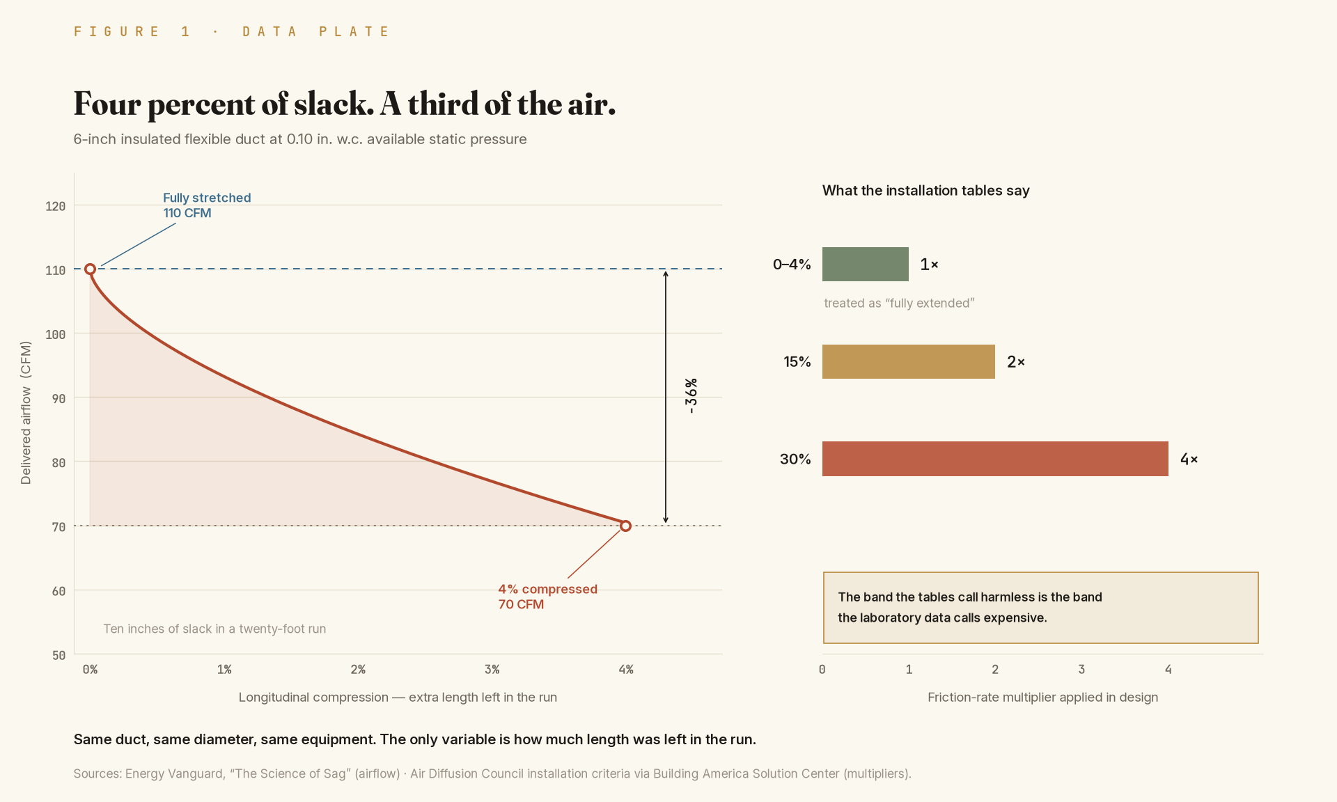
Source: Energy Vanguard, The Science of Sag; multipliers from Air Diffusion Council criteria via Building America Solution Center
Read the left panel first. A six-inch duct carries roughly 110 CFM when it is stretched tight, at a branch pressure of one tenth of an inch of water column — a very small push, about what it takes to lift water a tenth of an inch up a straw. At four percent compression the same duct carries roughly 70 CFM. Four percent of extra length, thirty-six percent of the air. That is the number this whole article turns on.
Now the right panel, which is the trade's own multiplier table. Zero to four percent compression: use the published friction rate as-is, a multiplier of one. Fifteen percent: double it. Thirty percent: quadruple it.5
Put the two panels beside each other and the problem announces itself. On the right, four percent is inside the “no penalty” bucket. On the left, four percent already cost a third of the airflow.
Where the paperwork and the measurement part company
The Air Diffusion Council's installation criteria, reproduced on manufacturer instruction sheets, group longitudinal compression into bands. Zero through four percent is labeled fully extended, and the designer is told to apply the published friction rate without adjustment. Beyond that, the multipliers kick in.5
The laboratory results do not draw the line in the same place. Texas A&M's testing under ASHRAE Standard 120-1999 found fully stretched flex within about two percent of rigid sheet metal, and found that beyond roughly four percent compression pressure loss ran two to ten times higher, with some configurations worse than ten times.2 The Berkeley work reached the same conclusion from a different direction and said plainly that the published design references understate the effect.1
So four percent is simultaneously the top of the bucket the tables call harmless and the bottom of the range the labs call expensive. Whether you get an honest design depends on which document your contractor's software was built around.
My read — and this is professional judgment rather than a cited position — is that the bands were never meant to describe the airflow a homeowner receives. They were meant to give a designer a workable friction rate for a duct assumed to be installed correctly, and “fully extended” was written as a specification of intent, not as a tolerance. A field installation that ends up at four percent has not met the intent. It has landed at the edge of the allowance, and the physics does not grade on the same curve as the table.
The practical consequence is that a Manual D calculation can be arithmetically flawless and still overpromise, because the friction rate it started from assumed a duct that was pulled tight.
Figure 2 · Two nominal sizes, given away

Source: Building Science Corporation, The Foibles, Follies and Fixes of Flex
This is the same physics stated as a purchasing decision. If your system was designed around eight-inch metal and installed in flex, the flex has to be nine inches in diameter to keep up — and that is assuming the good end of the compression range. At fifteen percent it needs to be ten. At thirty percent it needs to be twelve.
Almost nobody upsizes. The takeoff collar is eight inches because the drawing said eight inches, the flex is eight inches because the collar is, and the compression is whatever the day produced. The shortfall shows up months later as a warm bedroom, and by then it reads like an equipment problem.
The four conditions that put slack in a system
These are the four I look for, in the order they cost the most air.
1 · Slack in the liner. The run is longer than the path. The duct looks slightly wavy or accordioned rather than drum-tight between its supports. This is the condition Figure 1 is about, and it is the most expensive and least visible of the four.
2 · Sag between supports. The Air Diffusion Council criteria call for supports no more than four feet apart, sag no greater than half an inch per foot of spacing between supports, and support material at least an inch and a half wide. Vertical runs get support at least every six feet. A connection to rigid duct or to a plenum counts as a support point.4 Louisiana's weatherization field guide states the same four-foot interval and adds that the support must not crimp or reduce the interior dimension of the duct.9 Thin wire or a narrow zip tie carrying the weight of an insulated duct does exactly what you would expect: it necks the duct down at every support.
3 · Bends tighter than one duct diameter. The criteria call for a bend radius of at least one duct diameter, a straight section of at least one diameter before entering a bend, and additional support before and after a sharp bend.4 A hard ninety degrees coming straight off a takeoff, or a duct bent over a truss chord or a plumbing line, violates all three at once. ASHRAE's duct design guide makes the same point about bend radius and notes that poorly installed flexible duct is typically fifteen to twenty percent compressed.7
4 · Ducts lying on things, or buried in insulation. This one is climate-specific and it is the reason I am writing from New Orleans rather than from a textbook. In hot-humid climates, flexible duct should not rest on flat surfaces or be laid directly on the ceiling framing, because the contact surface becomes a condensation site. If ducts are going to be buried in attic insulation, the guidance is explicit — Building America recommends it and the DOE Zero Energy Ready Home program requires it: R-8 duct insulation first, then the duct encapsulated in at least an inch and a half of closed-cell spray foam, then at least two inches of blown insulation over that. The alternative in a vented attic is the opposite move: hang the duct up in the hottest part of the attic, where its surface stays above the dew point, rather than letting it sit cold against the ceiling.4 An August attic here runs 120 to 130 °F with outdoor dew points pushing 77 °F, which is a genuinely punishing place to run a cold surface.
Why this survives inspection
An inspector standing in an attic can see a duct crushed under a stored box. They cannot see four percent.
ASHRAE's duct design guide says so directly: improperly installed flexible duct “is difficult to detect, because compression is difficult to see or measure when installed.”7 That is a remarkable sentence to find in a design standard. It concedes that the single most common cause of underperforming branch runs is effectively invisible to visual inspection.
Which means the honest answer is not a better look. It is a gauge. Static pressure and airflow are both measurable in an afternoon, and neither one cares whether the duct looks fine.
| Installed condition | Friction multiplier | Flex diameter needed to match 8″ metal |
|---|---|---|
| Fully stretched | 1× | ~8″ flex |
| 4 % compressed | 1× per the tables | 9″ flex |
| 15 % compressed | 2× | 10″ flex |
| 30 % compressed | 4× | 12″ flex |
The middle column is the trade's table. The right column is the laboratory equivalence, at the same length and the same airflow — it is the width the flexible duct has to grow to in order to keep up with one eight-inch metal duct. Notice the two columns disagree in the second row, and notice that the second row is the row most field installations actually occupy.
Leakage is a separate account
Everything above is friction — air that never gets moving fast enough because the path resists it. Leakage is different: air that gets moving and then exits somewhere other than the room. The two get blended together in conversation constantly, and blending them makes both harder to fix.
Duct leakage is worth taking seriously on its own terms. Florida Solar Energy Center field work on Central Florida houses measured roughly twenty percent energy savings in both heating and cooling seasons from duct leakage reduction alone.10 That is a large number, and it is a different number from anything in Figure 1.
Keep them in separate columns. A duct blaster measures leakage. A pressure gauge at the air handler and a flow hood at the register measure friction and delivery. A system can pass a duct leakage test and still starve a bedroom, which is exactly the case that sends people looking at their equipment.
How connections should actually be sealed — what goes on first, what holds, and what quietly fails after a few years of hot and cold cycling — is a subject large enough to deserve its own note, and it is coming. Building Science Corporation's duct-sealing guidance is the reference I work from,8 and Louisiana's weatherization field guide is the local companion to it.9
What to measure, and what to ask
Five questions. They are all answerable with instruments a competent contractor already owns, and the answers are numbers rather than opinions.
- How hard is the blower having to push? The trade calls this total external static pressure, and it is read in inches of water column — pressure so small it is measured by how far it will lift water in a tube. Most residential equipment is built to work against about half an inch of it. A reading well above that means the system is fighting its own duct work.
- What is the measured airflow at the register in the room that is complaining? Not the calculated airflow. The measured one, at that register, taken with a flow hood — a capture box held over the grille that reads everything coming out of it.
- Was the Manual D designed for flexible duct or for metal? And if it was designed for metal and built in flex, was anything upsized. Figure 2 is the reason this question matters.
- Show me the supports. Four feet apart or closer, straps an inch and a half wide or wider, sag no more than half an inch per foot, nothing necking the duct down.
- Show me one boot connection. I want to see it properly sealed rather than held together with tape alone. How that is done well is its own subject, taken up separately.
If the answers to one and two are consistent — high static pressure and low delivered airflow — the distribution is restricting the system, and slack is the first thing I would go looking for. If static pressure is normal and airflow is low at one register only, that branch has a local problem: a bend, a crushed section, or a run that is simply too long for its diameter.
Read + model
Two calculators accompany this note. They model how installed condition changes delivered airflow through a given run, and they let you change the variables instead of taking a table's word for it.
- Flex duct airflow estimator — a homeowner-facing visual assessment built around the conditions above, plus a professional mode with sliders for diameter, length, compression, bend severity, and available static pressure. Draws the system curve.
- Duct installation calculator — the same physics with the math exposed: Reynolds number, the Haaland friction approximation, and the Darcy-Weisbach pressure loss, so you can audit every step.
Both are models. They are useful for understanding sensitivity — which variables move the answer and how much — and they are not a substitute for a measurement in your own house.
What this article does not say
- It is not an argument against flexible duct. Installed the way its own instructions require — pulled fully extended, supported at four feet or closer, no bend tighter than one duct diameter — it measures within a couple of percent of rigid metal, it is quieter, and it has fewer joints to leak. The case against it is a case against how it is often installed.
- It is not an argument that rigid metal is automatically better. Metal installed with too many fittings, undersized returns, or unsealed longitudinal seams will underperform a well-installed flex system. The material does not save a bad layout.
- It does not quantify your house. Every number here comes from laboratory testing or published installation criteria. What your particular runs deliver is a measurement, and the two calculators above are models of the physics rather than a report on your attic.
- It is not a claim that your contractor did this deliberately. Leaving a little extra length is the natural outcome of ordering duct in standard lengths and working in a hot attic, and the trade's own tables tell the designer that a small amount of it costs nothing. The gap between that guidance and the laboratory data is the failure here, not anyone's intent.
- It does not address duct leakage beyond flagging it. Leakage is a separate measurement with its own math, and it deserves its own note.
The part worth remembering
The distance between excellent and mediocre air distribution is often about ten inches of duct in a twenty-foot run — and it is invisible from the attic hatch, absent from the inspection, and forgiven by the design tables.
Which is why the only two questions that settle it are the two nobody asks: what is the static pressure, and how much air is actually coming out of that register. Everything else, including the choice of material, is downstream of those.
This note runs alongside Nº 005, How moisture reduces R-value, which takes up what happens when duct insulation gets damp, and Nº 009, The dew point doesn’t drop with the thermometer, which explains why a cold duct surface in a Gulf South attic is a moisture decision as much as a thermal one.
Sources & footnotes
Bass Abushakra, Iain S. Walker and Max H. Sherman, “Compression Effects on Pressure Loss in Flexible HVAC Ducts,” HVAC&R Research 10(3), 2004; Lawrence Berkeley National Laboratory. https://www.osti.gov/biblio/836654↩︎↩︎↩︎
Energy Systems Laboratory, Texas A&M University — flexible duct pressure-loss testing under ANSI/ASHRAE Standard 120-1999. Fully stretched flexible duct measured within approximately two percent of rigid sheet metal; beyond roughly four percent longitudinal compression, pressure loss measured two to ten times higher, with some configurations exceeding ten times. https://oaktrust.library.tamu.edu/items/88f0c264-13d4-4fc8-8023-5ad1ea7fa642↩︎↩︎↩︎
Allison A. Bailes III, “The Science of Sag — Flex Duct and Air Flow,” Energy Vanguard. Six-inch duct at 0.1 inch water column: approximately 110 CFM fully stretched versus approximately 70 CFM at four percent compression. https://www.energyvanguard.com/blog/the-science-of-sag-flex-duct-and-air-flow/↩︎
“Support at Intervals for Flex Ducts,” Building America Solution Center, Pacific Northwest National Laboratory, summarizing Air Diffusion Council Flexible Duct Performance & Installation Standards, 5th edition, §4.6 — supports no more than four feet apart, maximum sag one half inch per foot of support spacing, support material at least one and one half inches wide, vertical support at least every six feet, and bend radius at least one duct diameter. On hot-humid climates the same guide states that ducts cannot be laid on any flat surface such as the ceiling deck or insulation-filled joist cavities because of condensation on the outside of the duct, that ducts in vented attics should be hung in the hottest part of the attic to keep the duct surface above the dew point, and that “Building America recommends, and DOE Zero Energy Ready Home requires, that in all climates, if ducts are to be ‘buried,’ they must first be insulated with R-8 duct insulation then encapsulated with at least 1.5 inches of closed-cell spray foam insulation, then covered with at least 2 inches of blown insulation” (citing Shapiro et al. 2013 and Bailey and Swanson 2014). https://basc.pnnl.gov/resource-guides/support-intervals-flex-ducts↩︎↩︎↩︎
Royal Metal Products, flexible duct installation instructions, §4.5, reproducing Air Diffusion Council installation requirements: zero to four percent longitudinal compression treated as fully extended with a friction-rate multiplier of one, fifteen percent at two times, thirty percent at four times; ducts to be installed fully extended and not in the compressed state, and excess length not to be installed for possible future relocation. Copy retained in the project file repository alongside this article.↩︎↩︎↩︎↩︎
Building Science Corporation, “The Foibles, Follies and Fixes of Flex.” At 200 CFM and 650 feet per minute, and comparing diameters at equal length and equal airflow, an eight-inch round sheet metal duct is equivalent to nine-inch flex at four percent compression, ten-inch flex at fifteen percent, and twelve-inch flex at thirty percent. https://buildingscience.com/sites/default/files/4_the_foibles_follies_and_fixes_of_flex.pdf↩︎
ASHRAE, Duct System Design Guide, Chapter 2 — improperly installed flexible duct “is difficult to detect, because compression is difficult to see or measure when installed (Culp 2011)”; maximum sag one half inch per foot; bend radius greater than one duct diameter; poorly installed flexible duct typically fifteen to twenty percent compressed. https://hvacsimplified.in/wp-content/uploads/2021/09/ASHRAEs-Duct-System-Design-Guide.pdf↩︎↩︎↩︎
Building Science Corporation, Information Sheet 603: Duct Sealing — six-step flexible-duct-to-collar sequence, tie wraps drawn with a tensioning tool rather than by hand, mastic bridged to the boot vapor barrier, and the observation that cloth duct tape fails after hot and cold cycling. Copy retained in the project file repository alongside this article.↩︎
Southface Energy Institute, Louisiana Weatherization Field Guide, 2015, §3.1601.3a and §3.1602.1c — flexible duct supported at intervals of four feet or less using material at least one and one half inches wide, supports not to crimp or reduce the interior dimension of the duct; fiberglass mesh and mastic as the primary seal. Copy retained in the project file repository alongside this article.↩︎↩︎
Janet McIlvaine, David Beal and Philip Fairey, “Duct Repair in Four Occupied Manufactured Homes / Central Florida field study,” FSEC-CR-1256-01, Florida Solar Energy Center, 2001 — approximately twenty percent energy savings in both heating and cooling seasons attributable to duct leakage reduction. Copy retained in the project file repository alongside this article.↩︎