
This field note is for homeowners, contractors, and curious readers trying to understand what air movement does to insulation. The question is not whether convection is real. It is whether the explanation you are reading describes the part of the house you are trying to fix.
When the loops form, they move heat.
Convective looping is air circulating between warmer and cooler parts of an assembly and carrying heat along with it. In a wall, a loop can travel through connected gaps around the insulation. If the insulation is sufficiently air-permeable, circulation can also occur within the material itself. Those are related problems, but they are not the same path (Straube, Thermal Metrics, pp. 12–16).
“Warmer” and “cooler” are comparisons, not fixed temperatures. Under comparable pressure, the warmer air is less dense; that density difference can drive circulation. The important question is whether the assembly provides a path that allows it (PHP: Pressure Imbalances).
A loop does not require a leak carrying attic air into the room. Leakage through the enclosure, wind moving air through exposed insulation, and buoyancy-driven circulation within an assembly need to be distinguished before choosing a repair (Straube, Thermal Metrics, pp. 12–16).
Fiberglass, cellulose, and mineral wool are examples of fibrous insulation, but the names alone do not tell us how readily air moves through a particular installation. Material properties and quality of installation both matter, including density, fit, and gaps; “air-permeable” does not mean every product develops the same loop or suffers the same loss (Straube, Thermal Metrics).
Why the attic-floor research says winter.
Contractors and homeowners researching insulation may encounter convective looping in technical literature and industry education. It is a real, documented phenomenon, not an invented sales concern; the important step is keeping the explanation attached to the assembly and conditions studied (Straube: When R-Value Doesn’t Measure Up; Wilkes and Childs, 1992).
ASTM’s attic-insulation practice is titled Standard Practice for Determination of Thermal Resistance of Attic Insulation Systems Under Simulated Winter Conditions. “Winter” identifies the conditions addressed by that practice; it does not mean all convection is a winter problem (ASTM C1373/C1373M-23).
The Oak Ridge experiments behind the large R-value reductions studied a horizontal insulation layer with warmth below and cold above. That arrangement can drive buoyant circulation when the material and temperature difference permit it (Wilkes and Childs, 1992).
With a hot attic above a cooler room, the arrangement is reversed. Warm air is already on top, so the ideal horizontal layer is stable against that particular buoyancy-driven overturning. That does not stop heat passing through the ceiling, and it does not stop leakage or windwashing; it means the winter test is not a summer-attic penalty that can simply be carried over (Straube, Thermal Metrics; Wilkes and Childs, 1992).
The useful distinction is the direction of the temperature difference, not the month on the calendar. A cold night can put the warm side underneath the attic insulation again. Whether significant circulation follows still depends on the material and actual conditions, not the climate-zone label alone (Wilkes and Childs, 1992).
For our Gulf South work, my recommendation is not to make winter attic-floor looping the default explanation for poor insulation performance. Giving it that emphasis risks overstating the local problem and directing repairs toward the wrong cause. Start with the actual defects; consider looping where the assembly and conditions support it, including the attic-facing walls discussed below.
Keep the condition attached to the number.
Thermal resistance is the R-value actually measured under the test conditions, rather than simply the nominal rating stated for the insulation. Here is the finding worth retaining: in the tested loose-fill fiberglass system, Oak Ridge reported thermal resistance about 35–50 percent lower at temperature differences of 72–76°F than at smaller temperature differences. At differences of 20–30°F, the measured values were close to nominal. The larger difference was measured across the ceiling-and-insulation system, from the bottom of the gypsum board to the top of the insulation, not simply between a thermostat and an outdoor weather report (Wilkes and Childs, 1992, test methods and results).
That is a result for particular specimens under particular winter test conditions. It is not the temperature difference at which every insulation product first loses performance, and it does not tell us the percentage loss in a wall beside a hot attic. The same report did not find significant convection in the fiberglass batts and cellulose it tested (Wilkes and Childs, 1992).
For this Gulf South field note, I would not use that percentage to explain a homeowner’s uncomfortable upstairs room or justify an insulation replacement. I would first establish what assembly is there, where the air can move, and which problem the proposed work will correct.
The wall beside the attic is a different case.
A vertical wall has a warmer face and a cooler face beside each other, rather than one above the other. Air can rise on the warmer side and return down the cooler side if a suitable path exists. Connected gaps around poorly fitted insulation can provide that path; sufficiently air-permeable insulation can also support internal circulation (Straube, Thermal Metrics, pp. 12–17).
Here, an attic-facing wall means the wall separating a conditioned room from an unconditioned attic, whether it is full height or a three- or four-foot wall commonly called a knee wall. The practical requirement is continuous insulation and air control along that separation (PNNL: Attic Knee Walls).
There is direct wall-test evidence for this mechanism. National Research Council of Canada researchers tested eight-foot-square wood-frame walls with glass-fiber batts and different air-space arrangements. They measured additional heat transfer from buoyancy-driven air interchange between spaces on opposite sides of the insulation. The effect increased with temperature difference, air-space height, and insulation permeability; firmly fitting the insulation against one sheathing face greatly reduced the effect in the tested arrangements (Wolf, Solvason, and Wilson: Convective Air Flow Effects).
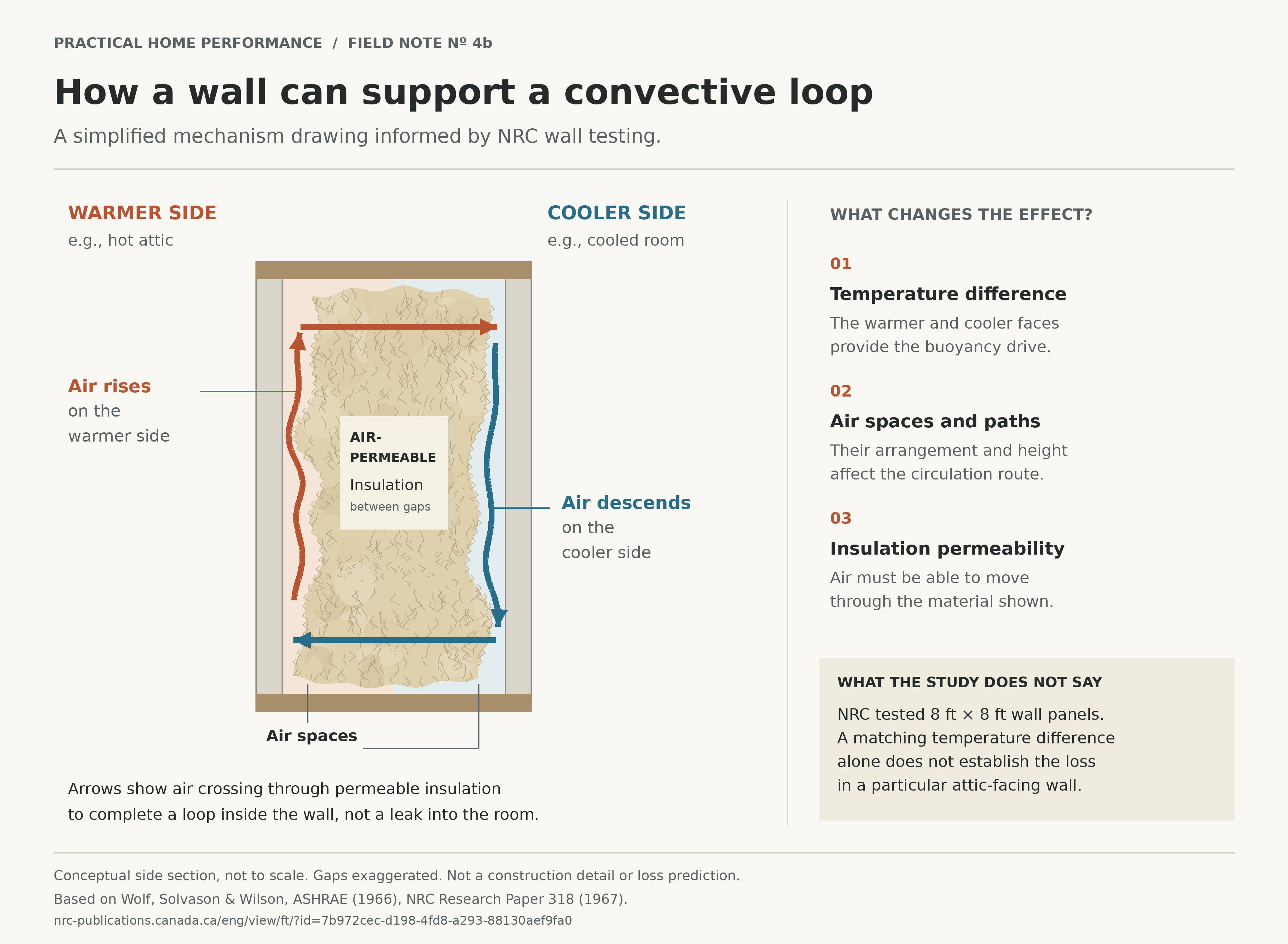
Those were controlled wall tests, not measurements of Louisiana attic walls. They support the mechanism: a hot attic can provide the warmer side of a vertical wall, just as winter indoor heat can. But a matching temperature difference alone does not establish a matching loss; insulation, gaps, and boundaries also have to be considered. The research supports checking an attic wall for the relevant paths, not assigning it the winter attic-floor percentage (NRC wall study; Straube, Thermal Metrics).
The visible defects are a more useful starting point: missing or sagging insulation, gaps around batts, an exposed attic-side face without suitable backing, or open floor-joist bays beneath the wall. PNNL’s repair guidance addresses insulation fit, continuous attic-side air barriers, sealed edges and seams, and blocking beneath the wall (PNNL: installation guidance).
For a closer look at gaps, voids, compression, and enclosure requirements, see RESNET Grades I, II, and III: What They Actually Look Like in a Real Louisiana Attic. That companion article explains installation quality; an installation grade by itself is not a measurement of convective looping.
Attic walls need insulation and air control.
Convective looping deserves attention at attic-facing walls when temperature differences and connected airflow paths allow it. The practical concern is not simply how much insulation is present, but whether air can circulate through or around it and carry heat across the wall. That makes installation quality part of thermal performance, not merely a matter of neatness (Straube, Thermal Metrics, pp. 14–17).
Air-impermeable insulation offers an important practical advantage: it can resist heat flow while blocking airflow through the insulation itself. Appropriately specified spray foam, or rigid foam detailed as a continuous, sealed layer, can combine insulation and air control. Product selection, installed thickness, and continuity matter; the material name alone does not establish a complete air barrier (PNNL: materials and installation).
That advantage still depends on workmanship. Gaps behind rigid boards, unsealed joints, and openings at edges can leave routes for air to circulate around an otherwise air-impermeable material. Good installation closes those routes as well as providing the intended insulation coverage (Straube, Thermal Metrics, pp. 14–17).
Properly fitted fibrous insulation with a continuous, sealed air barrier is also a supported approach. Whichever system is used, the priority is the same: complete insulation coverage, secure support, sealed connections, and closed bypasses at the top, bottom, and adjoining floor cavities. An effective attic-wall repair addresses both the insulation and the paths that let air undermine it (PNNL: Attic Knee Walls).
References
- John Straube, High Performance Enclosure Walls: The Limitations of R-Value (Research Report 0901).
- John Straube, When R-Value Doesn’t Measure Up.
- Wilkes and Childs, Thermal Performance of Fiberglass and Cellulose Attic Insulations (1992).
- ASTM C1373/C1373M-23: Standard Practice for Determination of Thermal Resistance of Attic Insulation Systems Under Simulated Winter Conditions.
- Wolf, Solvason, and Wilson, Convective Air Flow Effects with Mineral Wool Insulation in Wood-Frame Walls. NRC Research Paper 318.
- Pacific Northwest National Laboratory, Building America Solution Center: Attic Knee Walls.